Well noted. I find the clip with cable has one side with red dot which means pin 1. After reviewing the diagram from the manual of BCUSB, this side doesn't match with the diagram, which means the pin2 of the clip that will be connected to the SPI flash has no connection. It's so weird that my BCUSB can get a detection without matching with the diagram. Does this diagram have problem? Or is it possible that the red dot should be printed on another side?
You are using an out of date browser. It may not display this or other websites correctly.
You should upgrade or use an alternative browser.
You should upgrade or use an alternative browser.
Problem for flashing the SB6120
- Thread starter k045104
- Start date
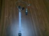
The red dot is correct in indicating it as Pin1 , you also have it connected correctly. The reason there is no connection to Pin 2 as per the diagram in the manual , is that in the manual it shows how to connect the chip if it was out of situe , in other words removed from the device as a standalone .
I think the best thing to do is solder the wires to the chip directly , to verify that there is no issue with the clip.
I think the best thing to do is solder the wires to the chip directly , to verify that there is no issue with the clip.
Hi D3m0n,
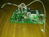
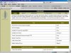
The result of soldering the ISP pin to the R362 keeps the same; however, I find something different at the status tab of the software. Can you help me confirm with your modem. I think the normal size of flash memory at this tab should show 8,388,608 bytes instead of 67,108,864 bytes. Is it possible that some sectors of the flash memory has damaged?
The result of soldering the ISP pin to the R362 keeps the same; however, I find something different at the status tab of the software. Can you help me confirm with your modem. I think the normal size of flash memory at this tab should show 8,388,608 bytes instead of 67,108,864 bytes. Is it possible that some sectors of the flash memory has damaged?
Attachments
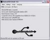
Regarding the flash size issue , you were using build310 which contained a few bugs , this error being one of them , in the Build312 which you used in the last screenshot you can see the issue is resolved.
Tell me if you use your BCUSB v1.4 do the LED's remain on when you connect the ISP pin as they do using your new V1.7 ?
Tell me if you use your BCUSB v1.4 do the LED's remain on when you connect the ISP pin as they do using your new V1.7 ?
Hi D3m0n,
My older BCUSB V1.4 was damaged as my computer can't find it. So, I purchased another new one which is V1.8. I just remember...When I used the V1.4 to flash the SPI flash, the software continued to read/write at the SPI flash tab even though I removed the ISP pin. When I first connected the v1.4 with the modem without using the ISP pin, only receive and send LED's couldn't go out; that is, if I push the ISP pin on the R362 spot, all of the LED's went out. As I was a novice, I forgot to continue to push the ISP pin, but the software continued to work. I don't know why and this flash process took me 2 hours to complete at the SPI Flash tab. As for the BCUSB V1.8, if I remove the ISP pin during the flash process, the BCUSB will not read/write unless I push the ISP pin on the R362 spot. It's so weird that the older BCUSB could read/write without using the ISP pin.
After that, I removed the clip from the modem and powered up the modem, the receive and send LED's were still on. So, I guess this problem has something to do with my older BCUSB which was damaged later.
Now, the SPI flash can be flashed with the BCUSB V1.8 without issues, but I can't make sure the inside memory does not have problem.
Hi D3m0n,
The seller allowed me to exchange but it isn't forceeware installed. So, I need to flash it in my end. When I finish flashing the modem, the webgui doesn't change which means the webgui still contains the default firmware of Motorola. However, I find something different that I can see a new tab "Open Source" after I flash it with forceware firmware. How do I see the forceware webgui? Thanks!
The seller allowed me to exchange but it isn't forceeware installed. So, I need to flash it in my end. When I finish flashing the modem, the webgui doesn't change which means the webgui still contains the default firmware of Motorola. However, I find something different that I can see a new tab "Open Source" after I flash it with forceware firmware. How do I see the forceware webgui? Thanks!
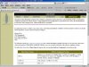
What script did you use to flash Forceware to the device ? Basically all that has happened is , Image 1 has been corrupted so it has reverted to Image 2 which just happens to have the Open source tab on it.
If you use the forceware script , you should be able to load Forceware correctly.
If you use the forceware script , you should be able to load Forceware correctly.
Share: