You are using an out of date browser. It may not display this or other websites correctly.
You should upgrade or use an alternative browser.
You should upgrade or use an alternative browser.
Problem for flashing the SB6120
- Thread starter k045104
- Start date
I do not think it is a total brick . There is not really anything you can test to see if it is completely faulty. But as you can still detect the flash there is hope .
When you flash the dumps to the modems do they remain constant or do they alter ... I noticed in your previous pictures that there was no power LED on , now normally with a bad flash you get all the LED's on but they are very dim.
When you flash the dumps to the modems do they remain constant or do they alter ... I noticed in your previous pictures that there was no power LED on , now normally with a bad flash you get all the LED's on but they are very dim.
Truly speaking, only power LED is on and the link LED is on when it's connected with my computer when it was first bricked from the ForceWare. After flashing with old version of PCB1.4, the power LED is off and the Receive and Send are on blue. Also, the link LED is dim blue without any connection with my computer.
Now, the LED's remain the same after I flash any dump file. I find the dump file doesn't apply with the modem, but it can be flashed successfully. What can I do for the next step?
Now, the LED's remain the same after I flash any dump file. I find the dump file doesn't apply with the modem, but it can be flashed successfully. What can I do for the next step?
Ok so it seems to be maybe just a flashing issue , what you can do now is to try and get some more flash dumps to try , If you got it pre-modded , try contact the seller and ask them if they still have the original dump of the modem .
I have to go to work now , so will be unable to reply until tomorrow sometime.
But try the dumps i sent you once again , as i know they are working dumps .
I have to go to work now , so will be unable to reply until tomorrow sometime.
But try the dumps i sent you once again , as i know they are working dumps .
if the LED's don't go out when BCUSB is connected using the ISP point , then it could be a bad connection or the device is faulty . Do you still get a detection even though these LED's are on ? Are you using a clip to connect to the SPI flash ? If so you could try soldering direct to the chip as the clips are unreliable
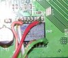
Yes, I get a detection and can read/write even though these LED's are on. I use the clip with cable to connect to the SPI flash, which purchased from C.U.S. Will the SPI flash be durable for the hot temperature if I solder it directly, like the photo?
These is one paragraph in the BCUSB manual listed below.
The image above shows you the pin outs of the 10-pin port and how it should be connected to
the SPI bus of your targeted device. Unlike JTAG mode, you can use the VCC pin to power
the target device. You should make note of the external power the chip needs and to make
sure you have that voltage selected on the BlackcatUSB board. Most SPI chips use the 3.3v
setting.
Since the SPI mode provides VCC pin to power the chip, why do we need to power up the modem during the flashing process?
Attachments
If you get a detection with the LED's on , it may well be a hardware failure on the device itself .
You can connect it as per the pic you posted , but if you add power to pin2 , you must not connect the modem power at the same time.
It is wise to use an external power source to add the VCC , cut up an old usb lead and use the 5v from that.
If you solder it up and solder the ISP point as well and the LED's still dont go out then i am afraid you may have a faulty device.
Share: