You are using an out of date browser. It may not display this or other websites correctly.
You should upgrade or use an alternative browser.
You should upgrade or use an alternative browser.
Unable to verify forceware firmware with BCUSB
- Thread starter bushe777
- Start date
bushe777
Member
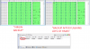
I think I'm not able to modify the modem at all, if the first backup and the one you asked me to make as it is, are exactly the same, then I'm not able to write anything to the flash. I have tried unchecking the verify option also but don't see any change when I go to address 0x040000, it should say "forceware"somewhere around there right. It is as if I don't have writing privilages and just read only access. However if the flash is untouched how come I no longer can access 192 site, I compared my 1st backup and a latest backup after doing a lot of things on the modem supposely, but they are perfect match from start to end.
Do you know a way to "factory reset" this modem? Like when you reset the TSOP on SB51XX by short circuit, is there something similar that makes the modem gets its default settings back as it seems I still have a good flash.
With the SBV6220.bcs script there is "Full" Read Area that makes a 16MB dump, don't see how this will be relevant since there is no write option for flashing it back or if this modem only has 8MB but will upload it anyways. Also I was able to compare it with my first backup and for the first 8mb they are exactly the same and after that my hex editor detect it as "inserted" but looking at them careful it is another exact copy of the first 8mb.
Attachments
bushe777
Member
I will try to get that info. I have been focusing on entering the modem for now, assuming flash is ok, link led blinks because it is transmitting data at most times, for some seconds it stays on and then blinks again. I have tried static ip's and also I can confirm that I'm able to ping to modem IP.
You should have access to the 192 page , as it gets an IP dynamic or static . Tell me does your browser just time out when trying to access the 192 page ? What i noticed as well is the dump that is on the modem now is actually your stock firmware , correct ? If that is so the n you should have the power LED solid and the next LED down should be flashing . The only time this does not happen with the 2nd LEd is when it has been flashed with modified firmware.
bushe777
Member
I had a weird case twice when I was connecting the clip and using SPI and taking it away and then turning the modem off and on, I'm not 100% sure how I got this behavior on the modem, I recorded this. Look at the video please and tell me if you are referring to that. Because in general I don't get 2nd led flashing, does this has to happen even if ethernet cable is not connected?
I will try to replicate this, but if I remember well I wasn't able to enter 192 still.
I will try to replicate this, but if I remember well I wasn't able to enter 192 still.
Attachments
bushe777
Member
I haven't been able to replicate that, but I'm certain it happened twice while touching the modem.
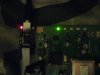
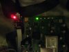
Other thing related to the bcusb and clip is that, I'm able to power the bcusb if it is connected to clip and modem to power supply, the red light isn't in its brightest as when it is connected to pc, but it gives it power and that tells something about the clip right, also if I only have the bcusb connected to pc and no power supply to modem I can make all 4 led get a green dimmed light. Sorry for the pictures but I had to take them on dim lighting to appreciate the leds.
Other thing related to the bcusb and clip is that, I'm able to power the bcusb if it is connected to clip and modem to power supply, the red light isn't in its brightest as when it is connected to pc, but it gives it power and that tells something about the clip right, also if I only have the bcusb connected to pc and no power supply to modem I can make all 4 led get a green dimmed light. Sorry for the pictures but I had to take them on dim lighting to appreciate the leds.
Attachments
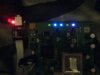
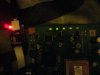
Yes that is normal , some power would be sent back to the BCUSB , In the last pic you have a few LED's on and they seem pretty bright , when does it get to this stage ? Also when you are trying to access the 192 page i am assuming you DO NOT have the coax connected ?
bushe777
Member
if you are referring to the picture "before using ISP pin.jpg" that is the stage when the clip is connected and then I connect bcusb to pc and at last I give power to modem. If I give power to modem first while having the clip connected and then connect bcusb to pc I get the 4 green dimmed leds from the moment I give power to modem and doesn't change after connecting bcusb to pc, so I have to turn the modem off and on again, or use the ISP and make then turn off and if I take the pin away is when they look like in the picture "before using ISP pin.jpg" that is what I always look to make it happen since this is what "verify me"that the modem will get detected.
Hope this explanation wasn't hard to understand lol.
I will try to make it in steps.
Case #1
To get power led on and red led of bcusb on (at start you will get 4 green dimmed leds that then turn off and leaves only power led on)
1. Connect clip to chip
2. Use modem's power supply
Case #2
To get 4 green dimmed leds constantly
1. Connect clip to chip
2. Connect bcusb to pc
Case #3
To get power/online leds green dimmed, send/received leds bright blue, link led purple
1. Connect clip to chip
2. Connect bcusb to pc
3. Use modem's power supply
You can go from case #1 to case #3 by making the ISP pin contact and release R362. You need to be on case #3 and then hold the ISP pin to R362 to detect modem.
Share: