William Humphreys
New Member
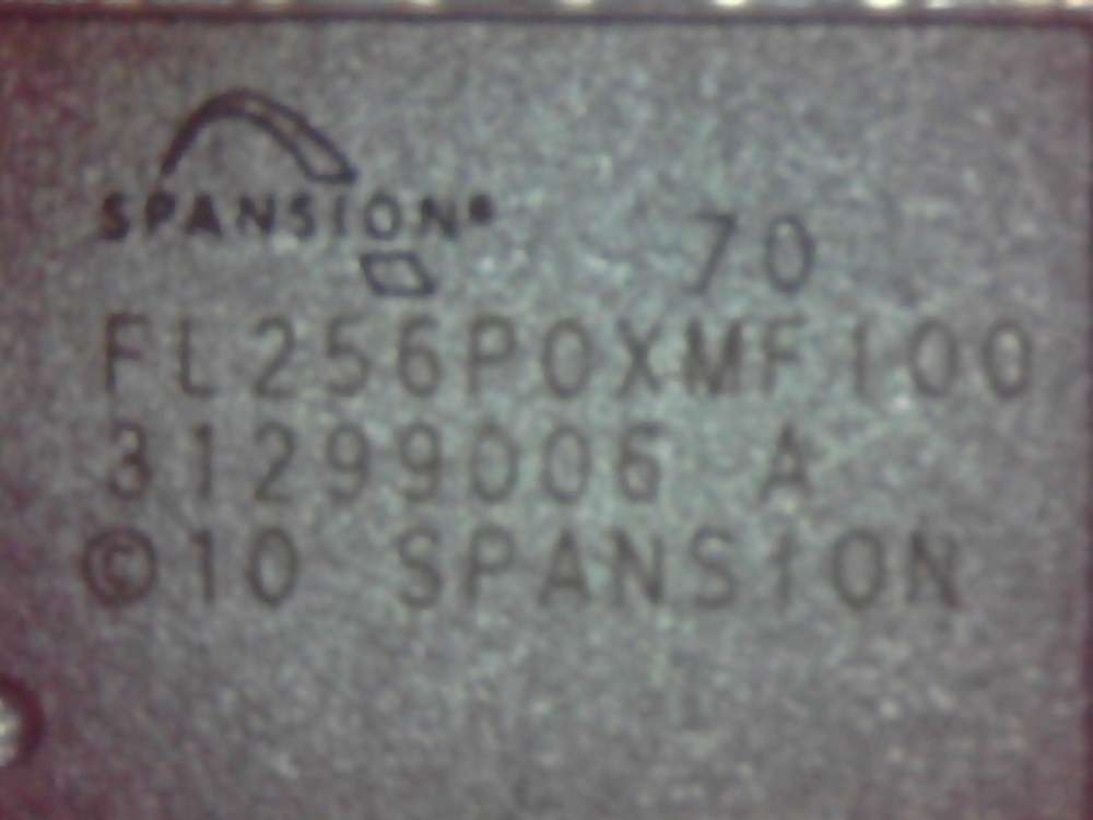
I’m trying to read (still soldered to the board) what I believe reading the writing on the chip is a Spansion S70FL256P. I’ve attached what I believe is the data sheet.
http://www.datasheetlib.com/datasheet/1371179/s70fl256p_spansion.html
The board it’s on is a cable modem (Netgear) but branded Virgin Media in the UK VMDG485 that I happened to have spare and don’t care about breaking. (I just had it spare so I figured it was what I would test the Flashcat with first)
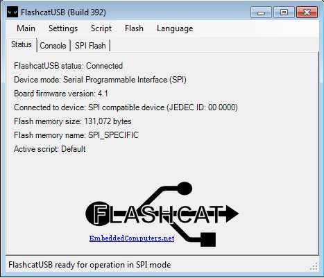
I’ve attached the Flashcat (SPI) by basically the way it describes in the manual.
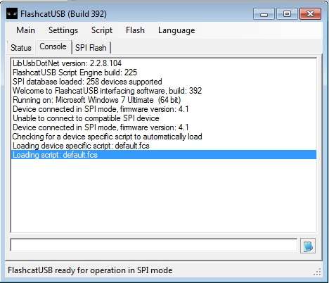
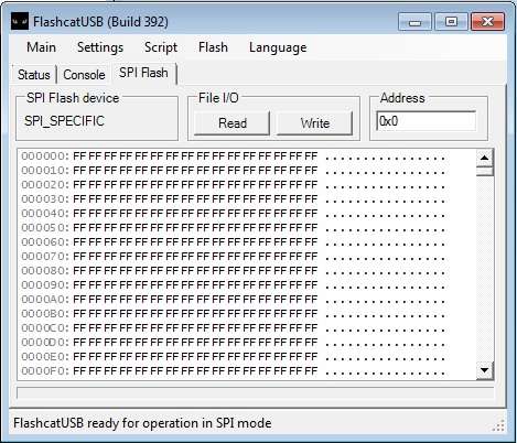
Now without attaching anything to VCC it won’t see anything. If I click “Use these setting” in SPI setting in then sort of sees something (Its sees the correct size of 1 of the 2 internal devices but it’s just like a blank chip, it will let me read it though there is no data) but I think it’s just the default script doing something. It doesn’t detect it with its real name either.
The board the chip is attached to ISNT powered (should it be?). Now when I attach the VCC (3.3) to VCC on its own and (also to pin one later as well) the software just disconnects and the lights on the device go daft (sometimes even messing up the driver and needing a reboot.
I also purchesed one of these to connect to the chip but I havnt had any luck with this either.
http://www.datahardware.co.uk/test-...ckcat-usb-spi-16way-test-clip-isp-sb6120-vmdg
I’ve asked around on a few forums but I get so many silly conflicting answers.
I’m assuming the device is working fine as I’ve re-flashed the device without issue and it does seem to do the “right” things after that.
Am I doing something daft here or does it need some config or suchlike?? I am a programmer so I would attempt to write a script but to be honest I get the syntax but not what I’m supposed to put in it.
It would be great if anybody could point out what SPI device commands relate to what setting in the data sheet then I may be able to do this for different chips in the future.
Being honest this is a great device if I can get it to do what it says on the tin.
My next test will probably be to de-solder the chip and attempt to read it but I thought I would ask yourselves first as it’s a pain to solder back on.
http://www.datasheetlib.com/datasheet/1371179/s70fl256p_spansion.html
The board it’s on is a cable modem (Netgear) but branded Virgin Media in the UK VMDG485 that I happened to have spare and don’t care about breaking. (I just had it spare so I figured it was what I would test the Flashcat with first)
I’ve attached the Flashcat (SPI) by basically the way it describes in the manual.
Now without attaching anything to VCC it won’t see anything. If I click “Use these setting” in SPI setting in then sort of sees something (Its sees the correct size of 1 of the 2 internal devices but it’s just like a blank chip, it will let me read it though there is no data) but I think it’s just the default script doing something. It doesn’t detect it with its real name either.
The board the chip is attached to ISNT powered (should it be?). Now when I attach the VCC (3.3) to VCC on its own and (also to pin one later as well) the software just disconnects and the lights on the device go daft (sometimes even messing up the driver and needing a reboot.
I also purchesed one of these to connect to the chip but I havnt had any luck with this either.
http://www.datahardware.co.uk/test-...ckcat-usb-spi-16way-test-clip-isp-sb6120-vmdg
I’ve asked around on a few forums but I get so many silly conflicting answers.
I’m assuming the device is working fine as I’ve re-flashed the device without issue and it does seem to do the “right” things after that.
Am I doing something daft here or does it need some config or suchlike?? I am a programmer so I would attempt to write a script but to be honest I get the syntax but not what I’m supposed to put in it.
It would be great if anybody could point out what SPI device commands relate to what setting in the data sheet then I may be able to do this for different chips in the future.
Being honest this is a great device if I can get it to do what it says on the tin.
My next test will probably be to de-solder the chip and attempt to read it but I thought I would ask yourselves first as it’s a pain to solder back on.